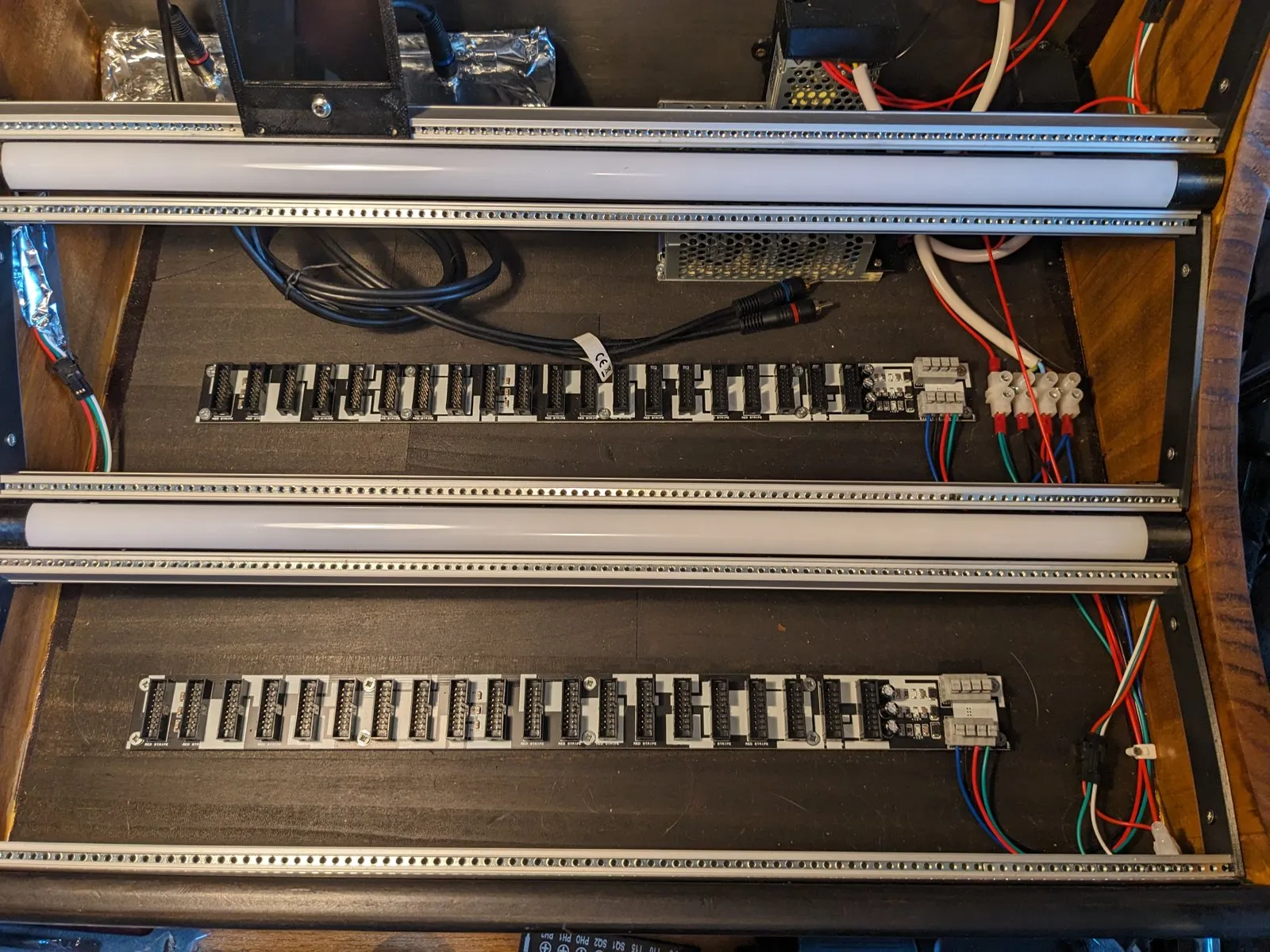
Wiring
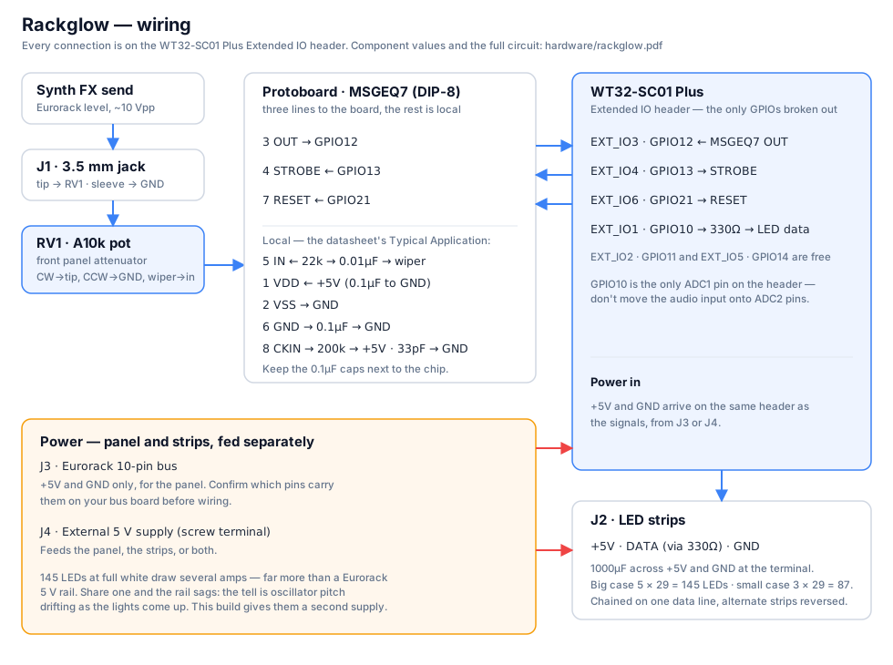
Everything connects to the board’s Extended IO header, which also carries +5 V and GND. These are the only GPIOs the WT32-SC01 Plus breaks out; the rest drive the display and touch.
| Header pin | GPIO | Connect to |
|---|---|---|
| EXT_IO1 | 10 | WS2812 data, through the 330 Ω resistor |
| EXT_IO3 | 12 | MSGEQ7 OUT (pin 3) |
| EXT_IO4 | 13 | MSGEQ7 STROBE (pin 4) |
| EXT_IO6 | 21 | MSGEQ7 RESET (pin 7) |
| EXT_IO2, EXT_IO5 | 11, 14 | free |
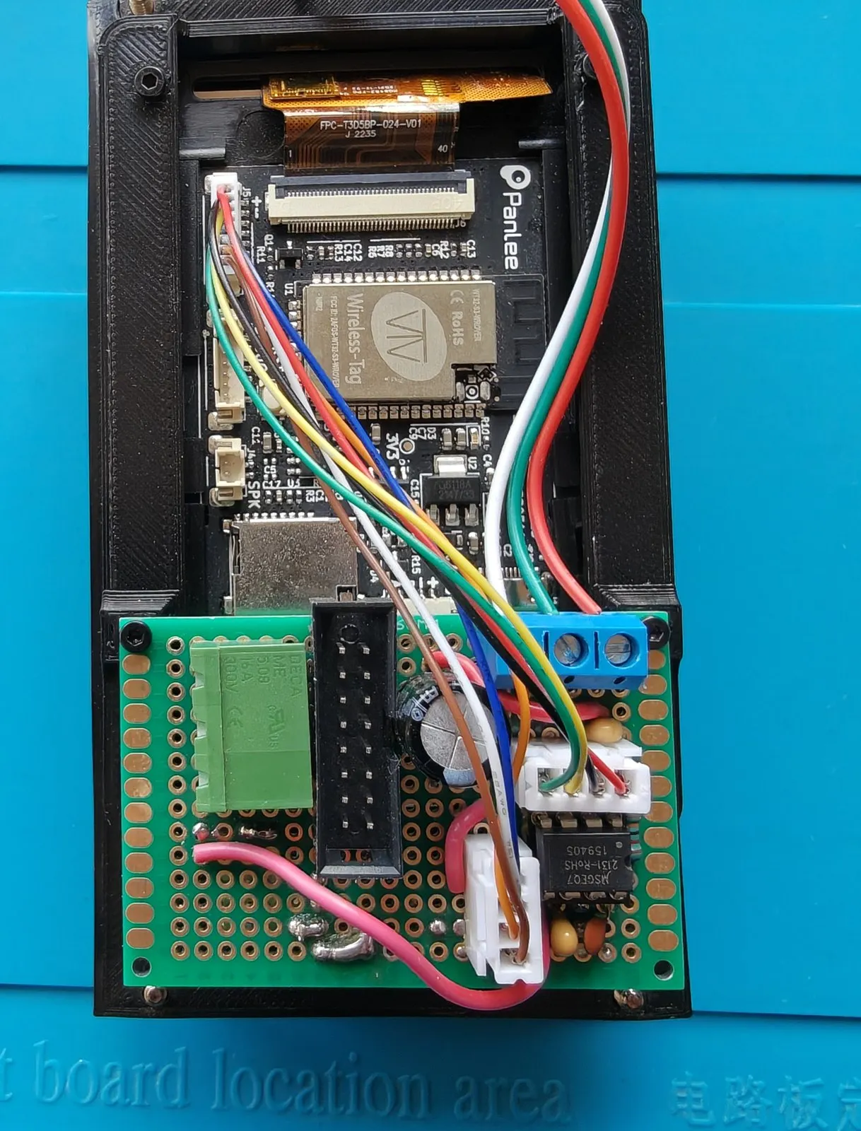
The MSGEQ7 board
Section titled “The MSGEQ7 board”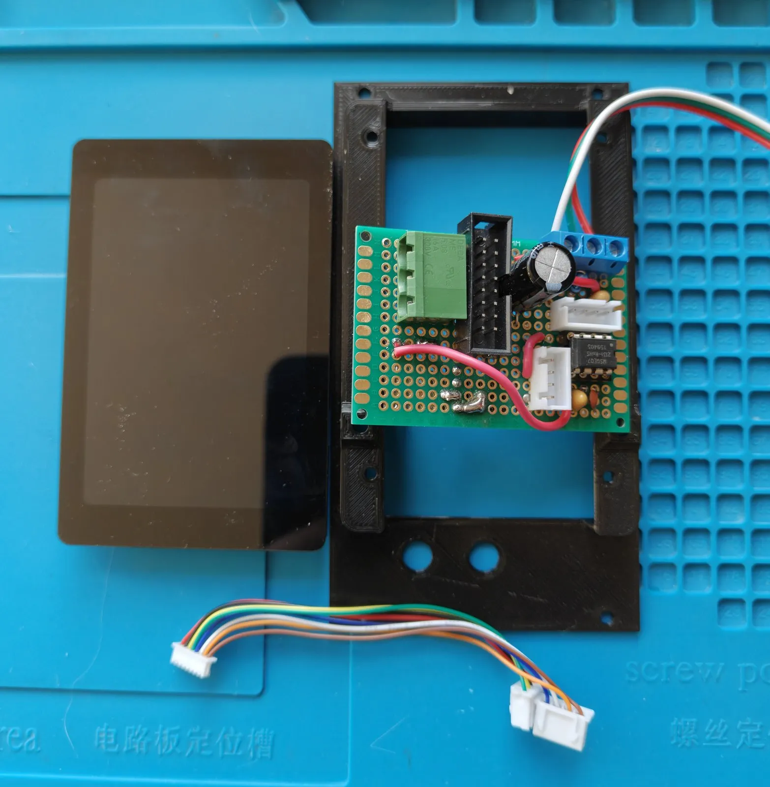
The circuit is the MSGEQ7 datasheet’s Typical Application, unchanged: 22 kΩ and 0.01 µF into IN,
0.1 µF on VDD, another 0.1 µF on pin 6 (the chip’s internal 2.5 V reference), and the clock set by
200 kΩ from CKIN up to VDD with 33 pF from CKIN down to ground. Keep the two 0.1 µF caps next to the
chip. The full schematic is in the repo as hardware/rackglow.pdf, editable in KiCad as
hardware/rackglow.kicad_sch.
Audio in
Section titled “Audio in”The jack takes a Eurorack-level signal — an FX send, in the reference build — which is around 10 Vpp, while the MSGEQ7 wants roughly 0.1–0.3 Vpp. The front-panel pot does that attenuation: turn it up until the loudest passage just reaches the top band without pinning, then back off slightly. Line level works too, with the pot further up.
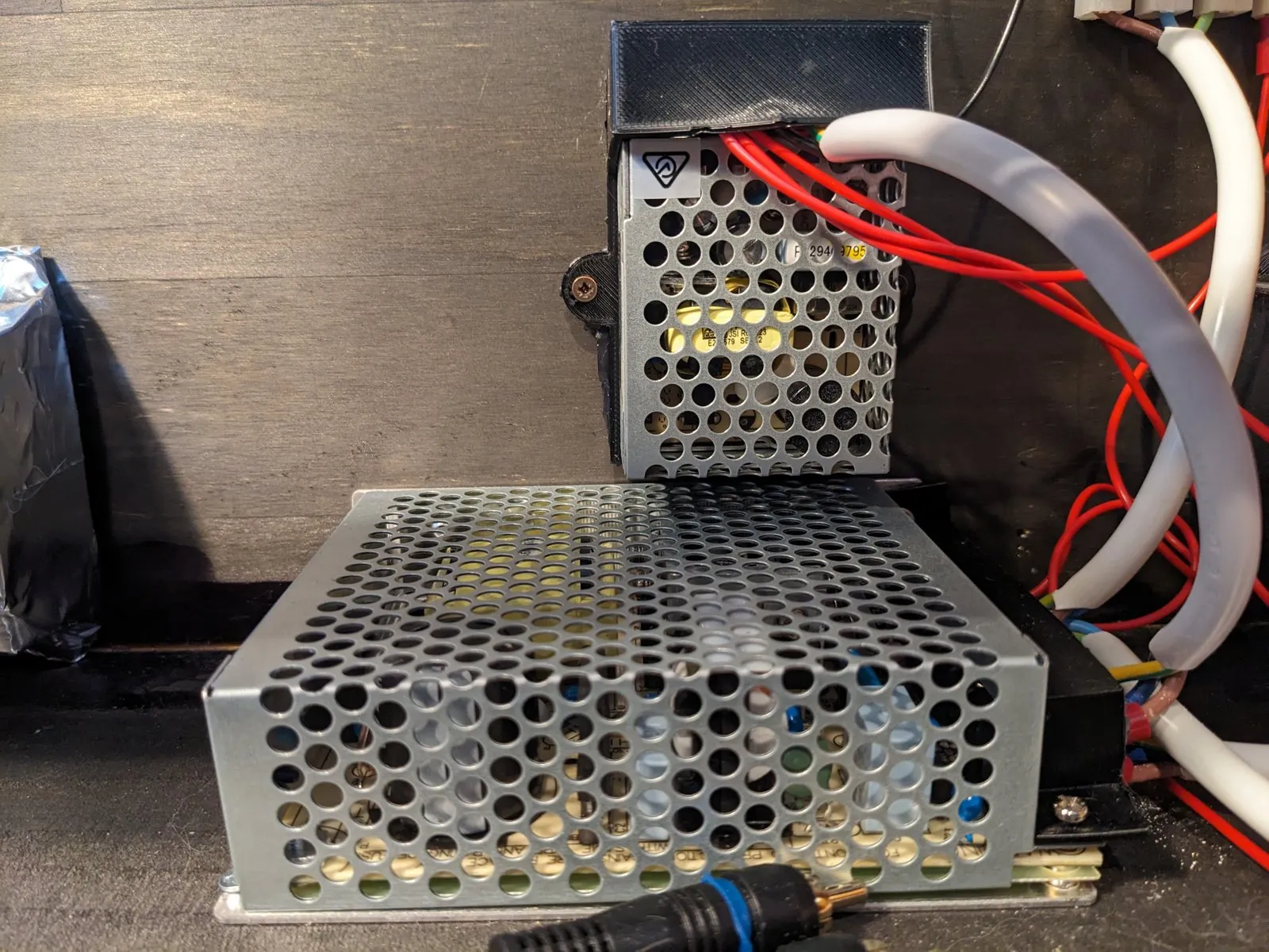
The panel and the strips are fed separately — the panel draws very little, the strips draw a lot.
| Feeds | Notes | |
|---|---|---|
| J3 · Eurorack 10-pin bus header | the panel | +5 V and GND from the case’s bus board |
| J4 · 5 V screw terminal | the panel, the strips, or both | An external supply |
The reference build uses two supplies: the case’s Eurorack bus powers the panel through J3, and a second 5 V supply drives the LED strips alone. One supply through J4 works too, if it is sized for the strips plus the board.
Strip layout
Section titled “Strip layout”Strips are daisy-chained on the one data line and treated as equal-length rows. Alternate strips run in opposite directions (serpentine), which is how they chain naturally behind a rail. You set the strip count and LEDs per strip in the web UI after installing.